FDC panel
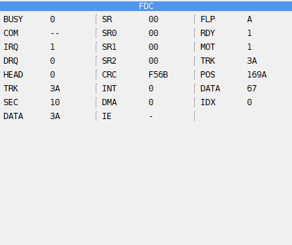
The FDC panel shows the floppy disk controller in its left and middle columns and the drive it works with in the right one. It is there only on a machine with a disk interface (see Floppy disks). All numbers are hex; a flag is 1 or 0. In the picture Fire ‘n Ice (n-Discovery, 2003) is loading from a TR-DOS disk: the controller reads a sector, command 80.
Field |
What it shows |
|---|---|
BUSY |
1 while the controller carries out a command |
COM |
the command it carries out; |
IRQ |
the controller’s interrupt request: the command has ended |
DRQ |
the data request: a byte is waiting to be read or written |
HEAD |
the side of the disk, 0 or 1 |
TRK, SEC, DATA |
the track, sector and data registers |
SR |
the status register |
SR0, SR1, SR2 |
the result registers of the +3’s controller |
CRC |
the checksum the controller has worked out so far |
INT |
an interrupt waiting on the +3’s controller |
DMA |
the DMA mode of the +3’s controller |
IE |
1 when interrupts from the disk interface are enabled |
Field |
What it shows |
|---|---|
FLP |
the drive the controller works with, A to D |
RDY |
a disk is in the drive |
MOT |
the drive motor is on |
TRK |
the track the head stands on |
POS |
the place on the track under the head, in bytes from its start |
DATA |
the byte under the head; |
IDX |
the index hole is passing: the start of the track |
Use it to follow a disk loader: step over the OUT that gives a command, then watch BUSY, DRQ and the registers as the command runs.